
Geometry
The Geometry window defines the second part of the first section in the lep file.

Raw data:
* Rib   x-rib       y-LE       y-TE         xp          z       beta         RP       Washin    Rot_z  Pos_z
 1      41.72       0.42     270.76      41.69       1.16       0.00      33.33       0.00      0.00   50.0
 2     124.64       3.78     268.69     124.07      10.33      10.00      33.33       3.00      1.95   50.0
 3     206.57      10.51     264.57     203.97      28.27      15.00      33.33       6.00      2.91   50.0
 4     286.98      20.74     258.41     279.31      56.16      25.00      33.33       10.00     4.75   50.0
 5     365.35      34.64     250.23     347.87      93.98      30.00      33.33       15.00     5.63   50.0
 6     440.64      57.63     239.83     407.14     140.22      45.00      33.33       20.00     7.97   50.0
 7     511.15      96.61     227.18     453.42     193.28      50.00      33.33       25.00     8.64   50.0
 8     575.50     148.95     212.80     473.45     254.62      90.00      33.33       30.00     11.31  50.0
These parameters can not be defined without a previous drawing, preferably in a file of computer aided design CAD, in which the desired plan is drawn to an appropriate scale, form lobe in elevation, and inclination of the ribs. This drawing is one of the most basic and important design (pre-process).
It would be possible to generate this drawing by a geometric preprocessor to read basic data from the wing desired number of cells, separation, size, shape, edge and trailing by a few parameters defined to create elliptical shapes. This pre-processor has been implemented. If you want to go this way you will find the data edit and processing functionality in lepg under Pre-Prosessor. However doing the wing outline with the help of a CAD application will give you much more degrees of freedom in your design. b
There is a limitation of not being able to define airfoils in the center of symmetry. To remedy this situation can be defined a virtual central cell’s with almost zero thickness.
The graphic below provides an overview about the individual parameters
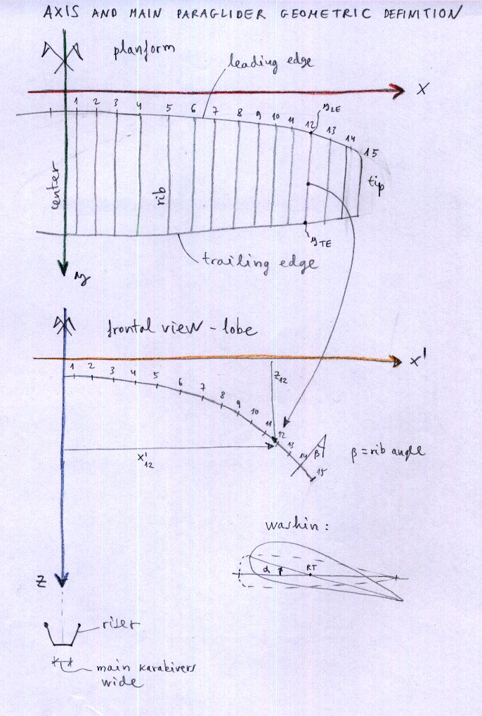
The 2nd last column defines the percentage to be taken into account if washing proportional to the chord (“1”) is selected in the Basic data window.
The last column defines the torsion angle for each single rib. You have to specify these values if you select Alpha mode “0” in the Basic data window.
Sort by Rib Number
The button Sort by Rib Number can be used to rearrange the definition lines. If for whatever reasons you will rearrange the lines, just define the rib numbering in an ascending order and press the Order button afterwards. Lepg will reorder the lines according to the numbering you’ve choosen.
ATTENTION you have to order the lines in a way that the wing is defined from the middle to the tip.
A more detailed description you can find here Laboratori d'envol website.